

While I was working on a blog post about Meshtastic (which will be online soon), I started questioning the time on air in a non-LoRaWAN context, where the online simulators I usually use did not work. This led me to investigate the LoRa frame format (not LoRaWAN, just LoRa, the underlying layer), and to confront the “sync word”, the functioning of a chirp… a whole range of concepts for which I expected to find abundant documentation. After all, in the LoRaWAN world, the open nature of the technology has been emphasized since its inception. However, after quite a bit of research, I still remain somewhat uncertain about the basic workings of LoRa, which at the very least calls for a blog post to compile the information I have found.
I invite those with a solid understanding of the subject to enrich this post with comments, and I will incorporate the key elements accordingly.
Preliminary Details on LoRa Chirps
The application note AN1200.22 LoRa Modulation Basics is very clear about chirps, and I will summarize the relevant information for this blog post as follows:
- A chirp is a unit of communication that sweeps either downward (down-chirp) or upward (up-chirp) through the frequency space allocated to the communication channel.
- A chirp encodes a value, with the number of bits it represents being related to the Spread Factor (SF). For example, a chirp in SF7 will encode 7 bits, while SF12 will encode 12 bits.
- The transmission time of a chirp depends on the Spread Factor, with the following relationship: Tc = 2^SF / BW. For example, a chirp in SF7 / 125kHz will last 128/125000 = 1.024ms.
- The raw data rate is therefore SF/Tc since each chirp carries SF bits. For the same example, the data rate would be 6.836 kbps.
- However, to reduce transmission errors, a forward error correction code is applied, referred to as the Coding Rate (CR). For example, 4:5 means that 5 bits are used to transmit 4 useful bits. The net data rate would therefore be CR*SF/Tc, in this case (⅘)*6.836 kbps = 5.27 kbps.
These are the basic mechanics and the easiest elements to find.
LoRa Frame Format
Now, let’s focus on the LoRa frame format, the one that carries higher-level protocols like LoRaWAN or Meshtastic. The key thing to understand beforehand is that the generation of this frame and the modulation of the chirps are handled by hardware provided by Semtech, which owns the LoRa technology. Therefore, there isn’t any open-source code available, except for the excellent work by CNLOHR, who used GPIO harmonics to achieve LoRaWAN communication. In doing so, they had to perform a significant amount of reverse engineering, resulting in a software implementation of the LoRa layer—likely incomplete, but still a well-advanced effort.
A quick search typically yields something like this when it comes to the format of a LoRa frame:
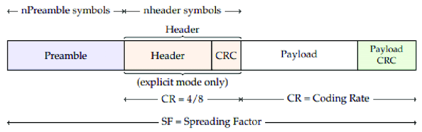
What is often presented is both correct and incomplete. Indeed, if I’m writing this article, it’s because I ran into difficulties with the concept of the sync-word, which isn’t typically mentioned, and the exact content of the header, which is rarely fully described. However, the following elements are essential to understand:
- Preamble: The LoRa frame starts with a preamble used for synchronization between the transmitter and receiver, but in reality, it’s more complex than that.
- Header: There is an optional header. When present, it’s called the “explicit mode,” and a CRC is optionally included at the end of the frame. If you want more control, you can use “implicit mode,” where the header and CRC generation are disabled. Switching between these modes on the Semtech chip enables or disables header creation and CRC calculation. Generally, explicit mode is used.
- Header Content: The header contains information such as data size and the Coding Rate (CR) used, but not the infamous sync-word. After the header, the payload and CRC follow, using the chosen CR.
The link between all this and the sync-word remains to be clarified. I read sometime that the purpose of the sync-word is to prevent decoding frames not intended for the receiver. For example, a device communicating in LoRa using Meshtastic does not want to process the more numerous LoRaWAN frames circulating. Instead of passing everything up to the MCU, which would be unnecessarily awakened, the radio chip is instructed to filter the messages, keeping only those using the correct protocol. This can work in certain situations but after getting clarifications from different experts, including Olivier Seller, the real role of the sync-word … is to sync the communications. It means that it is not to isolate traffic. So basically playing with the sync-word is dangerous. Then the sync-word can make some isolation but this one will depend on the signal straight and is not like a frame content filter. So, the best approach for filtering protocol is more to use header contents.
The sync-word operates at the lowest level and must be as early as possible in the frame. Since it has to work in both implicit and explicit modes, it cannot be located in the header. As a result, the sync-word is placed in what is often broadly referred to as the “preamble” in most representations of the protocol.
The publication hal-03200449 by V. Savaux, C. Delacourt, and P. Savelli has provided additional insights into the LoRa frame format:
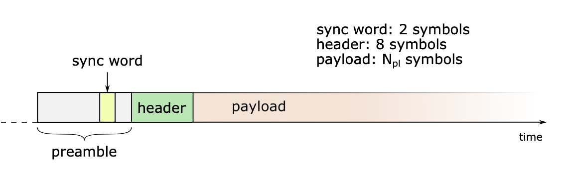
The sync word is part of the preamble and has a size of 2 symbols. We also observe that the header, in addition to having a specific Coding Rate (CR), has a fixed size of 8 symbols. This is an important detail because, while the duration of these two zones is fixed in terms of the number of chirps (I refer to chirps as what the publication calls “chirp symbols” or just “symbols”), the number of bits will vary depending on the Spread Factor (SF) used. (As a reminder, a chirp in SF7 encodes 7 raw bits, while in SF12, it encodes 12 bits.)
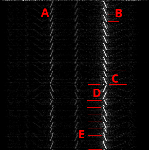
This can be visualized in CNLOHR’s description below. Zone B represents the up-chirps of the preamble, which are followed by 2 up-chirps in Zone C, representing the sync word, followed by 2.25 down-chirps marking the beginning of the header. All of this constitutes the preamble, showing us that a chirp is not necessarily unitary since we can have fractional chirps, like ¼ of a chirp.
The preamble zone before C usually lasts for 8 chirps, but this is a configurable parameter. For example, in Meshtastic, where devices are in “constant” listening mode, this preamble is doubled to allow the receivers to sleep periodically, thus saving some energy without missing messages.
The Sync Word
While we have discussed the utility of the sync word, it appears there are still a few mysteries surrounding it. To begin with, since it consists of 2 chirps at the radio level, its size ranges between 12 and 24 bits (SF6-SF12). According to hal-03200449, the sync word is not encoded. However, on the other hand, it is noted that the sync word is 1 byte on the SX1276 chips and 2 bytes on the SX126x chips, with a certain level of redundancy, as mentioned in the publication “LoRa Sync Word Compatibility” by Andreas Schweizer. This leaves me with a few open questions about the topic. I haven’t yet found a precise research document addressing how the sync word transitions from 8-16 bits, depending on the chip, to 12-24 bits, depending on the SF. Apparently only 4 of the bits of the sync word really comes from sync word register, other bits comes from different internal sources. The 4 other bits of that register have side effects able to prevent any further communications and not to touched. It seems that with a 16bits register, more should not be touched.
The LoRa Header
The header is quite well described in CNLOHR’s code or in the publication “Increasing the Performance and Applicability…,” and it can be represented as follows:

The header contains only a few pieces of information:
- The size of the payload (excluding the CRC),
- The Coding Rate (CR) used for the payload and the final CRC, which will trigger different algorithms and can take values between 1 and 4,
- A flag indicating whether a CRC is present at the end of the frame,
- A specific CRC for the header, allowing for its validation.
The header uses a Coding Rate of 4/8, minimizing the risk of errors upon reception, such that the 20 bits of the header are encoded over 40 bits.
Since the header always consists of 8 chirps regardless of the SF, the number of bits in the header is variable. In SF6, it contains 6 * 8 = 48 bits, while in SF12, it has 12 * 8 = 96 bits. Padding is applied based on the SF.
An important point is that radio communication is, in essence, a bit stream. Chirps group bits, but there is no concept of bytes or words as we typically think of them. Thus, you cannot reason in the same way as with a C structure, which aligns with word boundaries. This is worth mentioning because it can be quite confusing, especially in cases like this, where word size is dynamic while the structure is static.
For instance, in my schema above, the final CRC size is expressed in bits but is inserted into the bitstream of the payload. It will therefore be encoded into a variable number of chirps depending on the alignment (which depends on the payload size), the SF, and the CR used.
The “final” CRC only applies to the payload, as the header has its own CRC. An error in decoding the sync word could lead to the rejection of a valid frame or the acceptance of an invalid one, so this scenario seems possible.
Data Encoding
Beyond the transformation of bytes into chirps, there is a complex set of transformations applied to raw data before they are encoded into chirps. The publication “Increasing the Performance and Applicability…” describes these steps well and highlights the complexity of what is happening inside the Semtech chips:
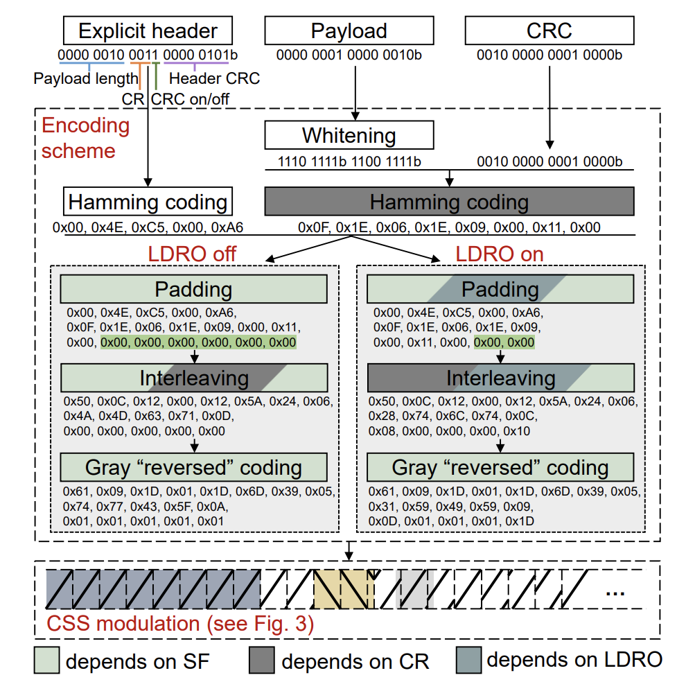
I won’t go into detail about these various transformations, as I haven’t studied them closely, but you can see that there are many steps, each of which depends on the frame fields and LDRO (Low Data Rate Optimization), which applies to higher SF values.
The whitening functions roughly switch bits with XOR operations on a pseudo-random basis to maximize bit flips in the bit stream. It randomize the bit patterns and reduce the possibility of long runs of 1s or 0s, which can cause problems in transmission.
The Hamming code corresponds to the choice of Coding Rate. Codes 5:4 and 6:4 (values 1 and 2 for CR) seem to be parity checks, while codes 7:4 and 8:4 (values 3 and 4 for CR) seem to be modified Hamming functions.
Padding aligns the bitstream with the number of bits involved in sending a complete chirp. Thus, the header, which always consists of 8 chirps, will be padded with zeros depending on the SF. Similarly, the payload may require alignment.
Interleaving essentially shuffles the bits within the block (header or payload) to improve resistance to noise. Since we use Hamming solutions capable of correcting 1 bit of error, it’s important to ensure that noise doesn’t affect more than one bit at a time within a protected group, as noise inherently tends to affect consecutive bits.
Finally, Gray “reversed” Coding divides the bitstream into words matching the size of the SF, such as 7 bits for SF7 or 12 bits for SF12. This aligns the data with the SF, enabling chirp-by-chirp transmission. Gray Coding then bijectively maps each value to another, ensuring that only a single bit changes when moving from one adjacent value to another. This facilitate errors to be corrected by the Hamming code.
Conclusion
LoRa still holds many secrets for me, but in general, it also remains a modulation technique with a lot of engineering behind it, aimed at optimizing noise resistance and reception performance, particularly when using low data rates. It is often summarized as chirp transmission, ignoring all of this complexity. I would love for its inner workings to be fully published so that we can grasp this intricate work more precisely. Sigfox did this on their side, so perhaps we just need to be patient 😉
In the meantime, the available encoding/decoding implementations (without using Semtech chips) still seem partial. But now, at least, I am able to calculate the “time-on-air” for Meshtastic frames!
Sources
- AN1200.22 – LoRa Modulation Basic
- Cnlohr LoRa on Gpio implementation
- Considering Sync Word and Header Error Rate for performance assessment in LoRa System – (hal-03200449)
- Lora Sync Word Compatibility – Andreas Schweizer
- Increasing the Performance and Applicability of LoRa through Chirp Emulation, Snipping, and Multiplexing
Salut Disk91,
Wow.. thanks a lot!
Believe it or not, I just started working on a LoRa (not WAN) project yesterday and I wanted to know transmission airtimes because of regulations here in Canada. It seems we are stuck at a maximum of 400ms per packets, once every 20s which is OK. We are thinking of buying spectrum licenses if needed as well.
So, I was working with my Signal Hound USB-SA44B and using Semtech’s online LoRa calculator in order to figure out if the calculator itself was reliable. Of course, measurements did not fit the calculator and I was having a hard time understanding the bitrate VS the actual payload bits until I realized there was some padding done as well.
They seem to be saying 0.25 symbol is the lowest logical unit, but are they really using it when converting the payloads into chirps? Unfortunately, my spectrum analyzer is not fast enough to figure this out. Maybe you can answer that.
We are using the SX1262, so the sync word is 2 chirps and we also have the 2.25 chirps that is hard-added by the SX1262. I want to explore how many chirps I could remove in the first recommended(?) 8 chirps for the preamble in order to reduce airtime.
I also think I will use implicit header mode (fixed payload lengths & CR) and disable payload CRC, since we already have FEC with the hamming coding. I think I will use 4/8 for that reason. We won’t know when we had errors, but packets will still be dropped when the number of faulty bits is too high. Since there is some interweaving that does not worry me much! So that would reduce airtime a bit more…
I will be at TTC 2024 in Amsterdam in September. I hope to see you there and discuss the Hidden Side of LoRa!
Merci pour ton aide,
Xavier
Will be nice to meet you at TTC 😉